Microcontroller with Python
Presentation slides can be found here.
Activity Goals
- Program a microcontroller in Python
- Interface electric circuits and microcontroller for input and output
Preface
We can build some amazing projects with microcontrollers, such as this gesture control robot and this robot arm. Microcontrollers are typically taught in second year of undergraduate programs; as such, the material in this session will get more and more challenging. However, by the end you should be able to follow tutorials online to make your own robot.
Introduction
A microcontroller is a mini-computer. A computer stores instructions in memory and executes them in sequence. A microcontroller is mini in the sense that it has smaller memory capacity, slower processor, and consumes less power. Normally microcontrollers are programmed to perform very specific tasks, such as tracking room temperature.
When we use a computer, we are actually interacting with a collection of programs that others have written and installed on the computer, known as the operating system. Similarly, to interact with a microcontroller, it needs to have a program already installed. We are going to learn how to program a microcontroller. Just as keyboards and monitors are the inputs and outputs for personal computers, sensors and LEDs are what we are going to use for our microcontrollers.
Arduino Hardware
We will use the Arduino Nano for this activity. Typically a personal computer would use a graphical user interface to display the state of the machine. By default on a Arduino Nano, we can only tell the state from the indicator LEDs.
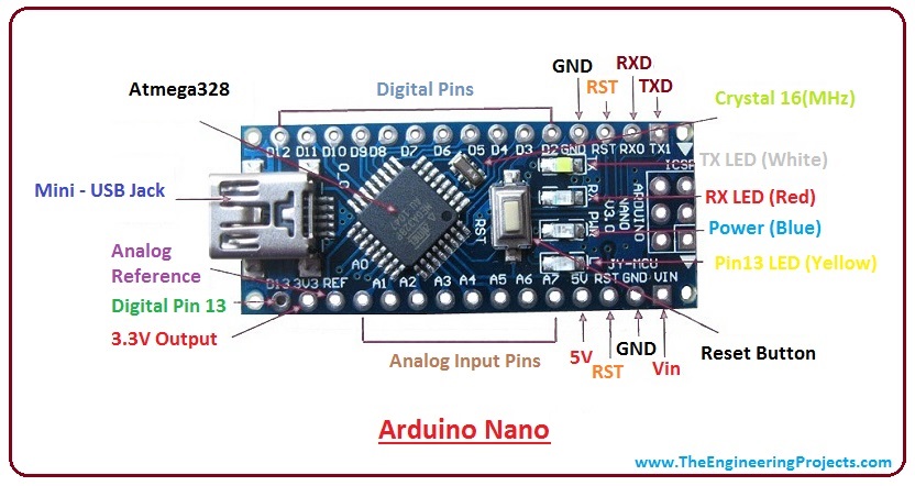
TX/RXtells us whether the board is transmitting or receiving data from the USB.- Pressing the reset button will clear the installed program on the board.
- Power is supplied through the USB when it is connected. Otherwise, it can also be powered through the
Vinpin by connecting it to voltage supply between 6V and 20V. Or through the5Vpin if the voltage supply is regulated.
Your Arduino Nano may look different slightly.
Circuit Components
LEDs
LEDs are short for light-emitting diodes. A diode can only pass electric current through in one direction; light is emitted when a current flows through the LED. Be careful that when current is forced to passed through in the opposite direction with high voltage, the diode will break and becomes ineffective. By convention, the longer terminal of a diode connects to high voltage and shorter terminal to ground.
Motors
A motor allows current to pass through in either direction. The direction of the current determines the direction of the spin. The speed is determined by the magnitude of the current.
Photoresistors
A photoresistor is a variable-resistance resistor, i.e. its resistance changes depending on the intensity of ambient light. The resistance ranges from 100 Ohms (bright) to 200 kOhms (dark).
Arduino Programming
Normally you will have to use a low-level programming language like C or C++ to program an Arduino, but Arduino-Python3 allows us to directly code in Python. How does Arduino-Python3 work? explains how we are able to program an Arduino in Python.
A typical script which we will write looks as follows.
"""
 exercise1.py
 Toggle Pin13 On and Off
"""

from Arduino import Arduino
import time

# initialize
board = Arduino()

# configure D13 as output
board.pinMode(13, "OUTPUT")

while True:
    # output 0V on D13
    board.digitalWrite(13, "LOW")
    time.sleep(1)

    # output 5V on D13
    board.digitalWrite(13, "HIGH")
    time.sleep(1)
2
3
4
5
6
7
8
9
10
11
12
13
14
15
16
17
18
19
20
21
22
Exercise #1 – Blinking LED
In this exercise, we will use the Arduino to output a digital signal to toggle an on-board LED.
Running Python Scripts in Spyder
We will be using the Spyder IDE (integrated development environment), which you should have used in the Python session, to write and run our microcontroller software in Python.
Plug Arduino to your lab computer via provided USB. You should see the power indicator light up in red on your Arduino Nano. Go back to the figure in Arduino Hardware section and locate Pin13 LED on your Arduino Nano.
Open a new file in Spyder. Copy and paste the code above into text editor area, and then save the file as
exercise1.py.Execute the code in Spyder. At this point, you should see the Pin13 LED starting to blink in one second intervals. If not, check with session or camp leaders.
Once you have confirmed that the LED blinks in one second intervals, stop running the Python script by pressing a red square button on the right-hand panel.
Questions to Think About
- Look at the code again. Is this what you thought the code would do?
- What do you think will happen if you delete line 13 in
exercise1.py? Try it! - What do you think the line
time.sleep(1)does? - Try changing both line 18 and 22 to
time.sleep(0.1). Do you know whattime.sleep(1)does now? - Press the physical reset button on the Arduino. What does it do? Press it several times. Did anything break? Does the LED still blink?
Exercise #2 – External LED
In engineering, there is a saying "To find the answer, you must first know the answer." Try to answer the questions, or come up with a guess, at the end of each exercise before you follow the steps. Once you have an answer, do the exercises to confirm or modify your answers.
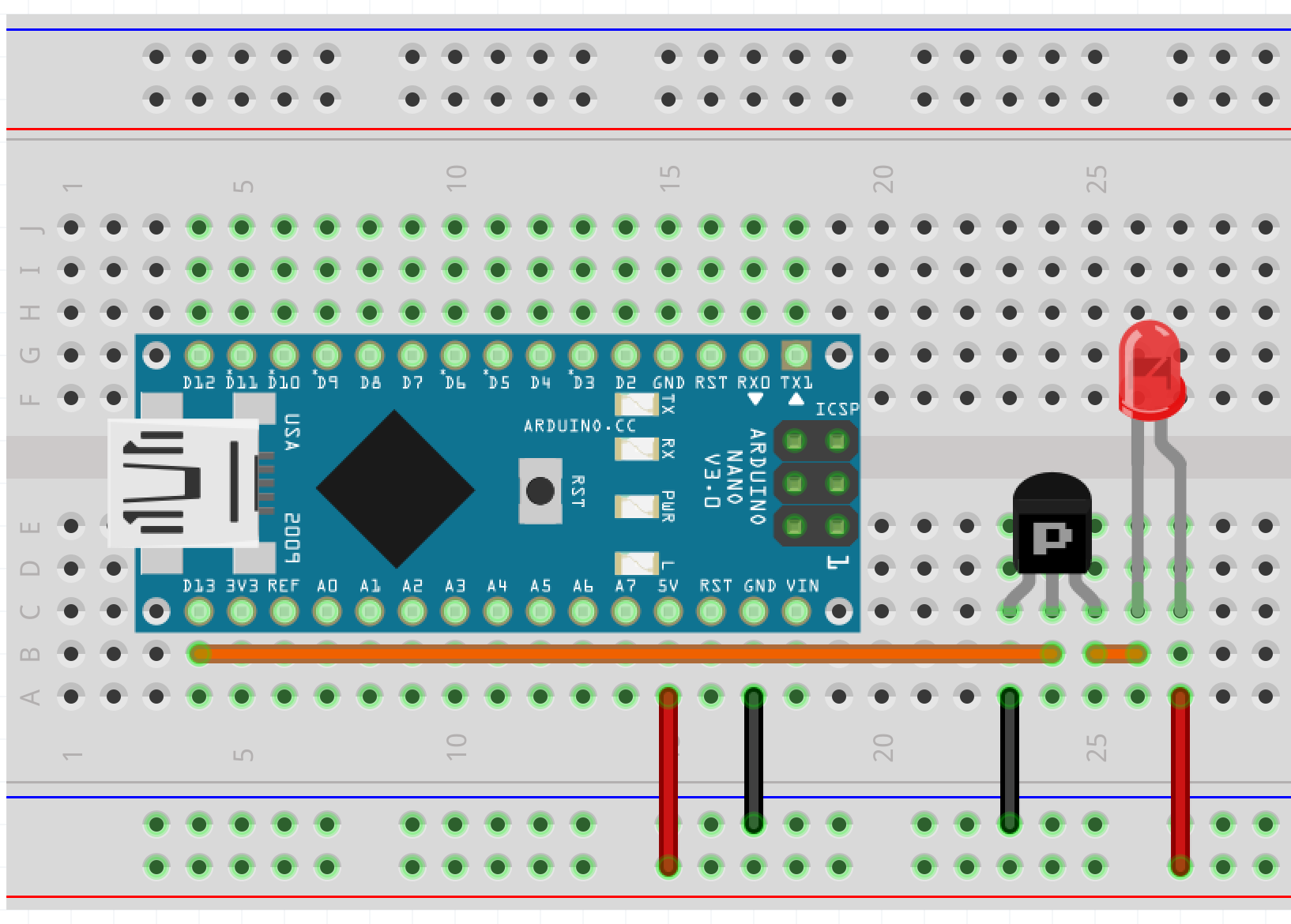
In this exercise, we will blink an external LED with the Arduino. It will also refresh the circuit knowledge you gained from earlier this week.
First, disconnect USB from the Arduino. You should never connect electric components with currents running through the circuit. Although the voltage is not high enough to hurt you, it will potentially damage the components.
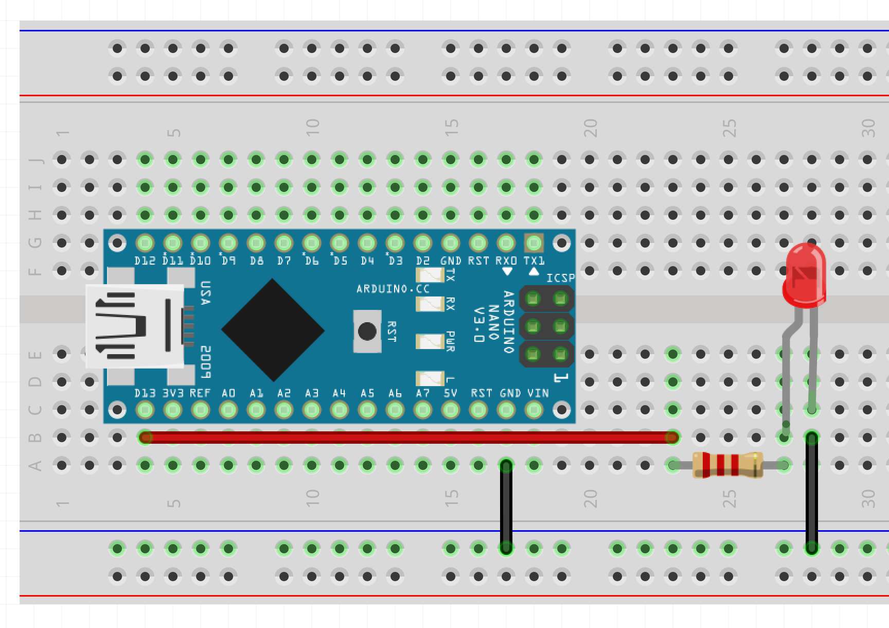
Set up your board as in the picture below. Pay attention to the long and short end of the LEDs and make sure they are connected correctly. Usually it is easier to trace from one end to the other: start from voltage source (D13) → 2.2k resistor → long end of LED → short end of LED → ground.
Run
exercise1.pyin Spyder and confirm that the newly connected LED flashes in sync with the Pin13 on-board LED. Afterwards, stop the Python script in Spyder.Modify
exercise1.pyto output signal on D2 instead. Make sure to disconnect USB from Arduino and rewire the circuit to use the D2 pin.
Colour-coding Wires
By convention black and grey wires are reserved for connecting to electric ground on the circuit board. Red and orange wires are usually used to connect from power, and blue and green wires are used to indicate signals. The colours really help when the circuit board starts becoming filled with wires.
Questions to Think About
- What happens if you don't connect one of the black wires in the diagram above?
- What happens to the LED if you replace the resistor with a wire?
Exercise #3 – Analog Read
So far, we have only been outputting signals from the Arduino. In this exercise, we will learn to read signals from a photoresistor.
Analog vs. Digital Signals
Analog signals are continuous-valued. For example, the normal room temperature might be anything between 15C and 25C. The temperature can be any value inside this range, so it is continuous. Digital signals are either high or low corresponding to 1 (on) or 0 (off). Typically, the values are represented on eletronics as voltages, where low is 0V and high is either 3.3V or 5V.
Voltage Divider
We will put the photoresistor in a voltage divider. Using an analog pin on the Arduino to read the voltage values at the middle of the divider allows us to detect changes in ambient brightness.
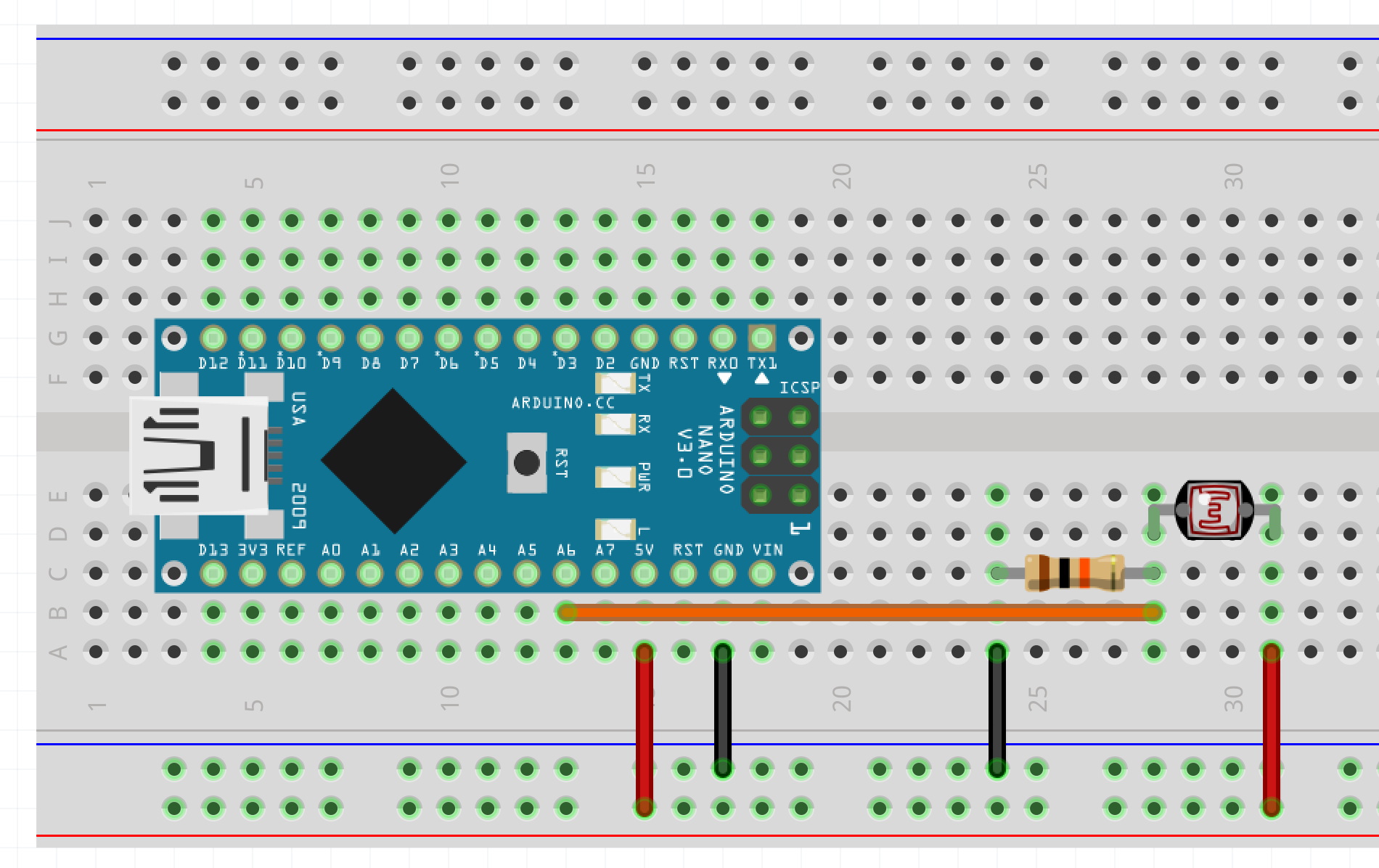

First we put the photoresistor and resistor in a series (one after the other from voltage source to ground) connection. In a series connection, the resistance each component is added together .
We can get the voltage at A6 by multiplying and .
Since and are constant, we will get different voltage readings when changes resistance.
Reading Analog Signal
To read the analog signal at A6, we just need to configure the pin as input and use the analogRead function. We will store the returned value in a variable and print its value in the next line.
"""
 exercise3.py
 Reading from photoresistor
"""
from Arduino import Arduino

board = Arduino()

PHOTO_PIN = 6

# Using A6 as input pin
board.pinMode(PHOTO_PIN, "INPUT")

while True:
    # value is between 0 and 1023
    photo_value = board.analogRead(PHOTO_PIN)
    print(photo_value)
2
3
4
5
6
7
8
9
10
11
12
13
14
15
16
17
Constants and Variables
In Exercise #1, we use the value 13 (for D13) in three different lines. It is much easier to tie the value to a variable such as PHOTO_PIN. This way we only need to change one line if we ever want to change it to another pin. Unlike some other languages, Python does not distinguish between constants and variables. If we know the value to a variable will not be reassigned later in the code, then by convention we make the variable name all uppercase to indicate that it is a constant.
Unpower Arduino and connect the circuit above. Again, trace from voltage source to ground to make sure everything is connected properly.
Paste the code above to a new file in Spyder and save as
exercise3.py. Run the script and observe the changing values when you cover the photoresistor with your hands.
Questions to Think About
- The value that we are printing is discretized between 0 and 1023 according to Arduino Nano's analogRead() Reference. A true analog signal should be able to take on any value between 0 to infinity, such as 2134.536. Discretize means that the signal can only take on whole number values 0, 1, 2, ..., 1022, and 1023. Does it ever go outside this range? What are the maximum and minimum values that you can get it to print?
- For a given printed value, say 800, can you figure out the resistance of the photoresistor?
- (hard) How does the choice of the 10k resistor affect the analog reading? Hint: Look at the voltage divider equation. What happens if we used an extremely high value? What happens if we used a value close to 0?
Exercise #4 – Analog Write
In this exercise, we will learn to output analog signals using Arduino's pulse-width modulation (PWM) support. A digital signal is either 5V or 0V. But with a analog signal, we can output anything in between, such as 2.2V. By controlling the output voltage, we can control the brightness of a LED or make a motor spin faster or slower.
Pulse-Width Modulation
The central idea of pulse-width modulation is to control signal magnitude using duty cycles, as depicted in diagram above. When the duty cycle is at 100%, then we have a constant on signal which we can think of as equivalent to a digital high signal. Similarly, duty cycle of 0% is equivalent to a digital low signal. When the duty cycle is at 50%, the signal is on and off for half the time respectively. We can consider the average voltage across a long enough time period to be 50% of the high voltage – In our case, it would be 2.5V (50% of 5V). By adjusting the duty cycle, we can control the voltage we want to output.

For most coding projects that happen in the real world, it is very unlikely that anyone will write every line of code from scratch. Therefore, one of the most important skills in programming is being able to read documentations and find answers online.
From analogWrite() documentation, we see that Arduino Nano can write analog values using Pins 3, 5, 6, 9, 10, and 11. Furthermore, the value parameter to the analogWrite function takes on integers betweeen 0 (always off) and 255 (always on).
"""
 exercise4.py
 Outputting analog signals
"""
from Arduino import Arduino
import time

board = Arduino()

# TODO: Configure D3 to be output

while True:
    # TODO: Use `analogWrite` to output 2.5V
    # First ?? is the pin number
    # Second ?? is the PWM duty cycle value
    # board.analogWrite(??, ??)
    time.sleep(0.1)
2
3
4
5
6
7
8
9
10
11
12
13
14
15
16
17
18
Using information above to fill in the missing code in the given snippet and save as
exercise4.py. It may help (but not necessary) to also check out the Arduino-Python3 documentation onArduino.analogWrite()method.Once you have completed the code, assemble a circuit similar to the one in Exercise #2 using an LED and a resistor. Remember to power off first!
Run the code with circuit connected. Try outputting different analog values.
Questions to Think About
- Would outputting 2.5V to an LED cause it to shine brighter or dimmer than outputting 5V?
- Can you think of other scenarios where you might want to output an analog signal rather than a digital signal?
- (hard) When introducing PWM, we mentioned for a long enough time period. What does long enough mean? What is the duty cycle period for Arduino Nano?
Challenge Problems
Come up with questions that you do not have the solutions for and answer them by conducting experiments. Think of creative ways to combine the eletronic components you have. This section contains some challenging problems to get you started.
One of the characteristics you see among great scientists is that usually they had independent thoughts, usually when they are young, and had the courage to pursue them. Albert Einstein, around 12 or 14, asked himself the question, "What would a light wave look like if I went with the velocity of light to look at it?" This question would later guide his work on special relativity.
Problem #1 – Adaptive Lighting
(Difficulty: Medium)
In Exercise #3 and Exercise #4, we saw how to read from a photoresistor and adjust LED brightness using analog writes. Combine the two exercises to create a circuit that adjusts the intensity of a LED depending on the ambient brightness.
Hints
analogRead()returns values between 0 and 1023.analogWrite()needs values between 0 and 255. Do the values 1023 and 255 have anything in common? How about 1024 and 256?
Problem #2 – Controller Timing
(Difficulty: Hard)
Remember the time.sleep() function call we used in Exercise #1? It is not ideally for responsiveness purposes to have sleep() calls in the main loop of a controller.
Consider the code below. toggle_every_second() is toggles pin D13 every second as intended, but read_photoresistor() is executed only once every two seconds because of the time.sleep() calls in the previous function. How can we change it so that the LED still toggles every second, while reading photoresistor as frequently as possible?
# Some setup code omitted...

def toggle_every_second():
    board.digitalWrite(13, "LOW")
    time.sleep(1)
    board.digitalWrite(13, "HIGH")
    time.sleep(1)

def read_photoresistor():
    return board.analogRead(PHOTO_PIN)

while True:
    toggle_every_second()
    value = read_photoresistor()
2
3
4
5
6
7
8
9
10
11
12
13
14
Hints
- You may find
time.perf_counter()in the Python's time library documentation helpful. You may also need to use an if-else statement, similar tomirror_state()in the next problem. - The LED into two states: on or off. Are there two categories that every whole number naturally falls into? Is there a convenient operator that separates numbers (time) into two these categories?
Problem #3 – State Machines
(Difficulty: Easy with Problem #2 completed, otherwise hard)
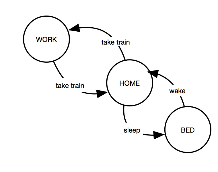
Not all controller are time-based. State machines are useful abstractions for coding all kinds of controllers. An example of a state machine is illustrated below. Each circle is a state, each state has its associated action(s) represented with arcs, and each action leads to the next state.
Code up a simple state machine with if-statements to control two LEDs. The first LED will be toggled based on time, and the second LED will mirror the state of the first LED. If first LED is on, then second LED should be off and vice versa.
Pseudocode
All programming languages follow some kind of syntax and grammar. For purpose of explaining, it is often easier to write pseudocode instead complete code. <led1_on> (in snippet below) is not valid Python syntax; it is only meant to be understood by human readers.
# Setup code omitted...

def toggle_every_second():
    # code from Problem #2

def mirror_state():
    if <led1_on>:
        # turn led2 off
    else:
        # turn led1 on

while True:
    toggle_every_second()
    mirror_state()
2
3
4
5
6
7
8
9
10
11
12
13
14
Problem #4 – Battery and Motor
(Difficulty: Easy)
In Robotics, usually there are at least two circuit boards – controller and driver board. The controller board is usually a microcontroller like the Arduino we have, or some kind of mini-computer such as Raspberry Pi. Suppose we are building an autonomous drone, the job of the controller is to process the terrain information and output commands, such as turn left, accelerate, and stop, to navigate through the terrain. Usually the controller does not support enough voltage and current to drive heavier components, such as a motor. Therefore, a driver board with a separate higher power supply is used to drive these components.
Typically the controller outputs digital signals to some kind of switch on the driver board. The switch controls whether a device, ex. motor, is on or off. For our purposes, we will use a transistor to serve as a switch.
N-channel Transistor
Transistors and Water Analogy
Transistors are typically taught in second or third university circuit courses. A transistor is definitely more than just a simple switch. For easier understanding, check out the water analogy article on SparkFun.
A transistor is a three-terminal device, which are source, drain, and gate. In the diagram below, the source is connected to a LED then to 5V, the drain in connected to ground, and the gate is connected to D13. When the gate voltage is 0V, the transistor is off. In this case, there is no current flowing through from the source to drain, so the LED should be off. On the other hand, the transistor can be turned on by applying 5V at the gate. In this case, current will flow from 5V → LED → source → drain → ground, which will turn on the LED.
For this problem, set up a transistor switch circuit with a motor. The motor should be driven with 9V (although it will still work with 5V because the motor we have is small). Drive the motor on and off with a digital signal using the Arduino.
Hints
- Even though we have everything on one circuit board, there are actually two separate components. The motor + transistor + battery circuit can be set up independently of the Arduino. Once both components are done, just hook up a wire from a digital pin to the transistor gate.
More Information
Congratulations, you've made it to the end! To learn more about microcontrollers, Arduino has comprehensive tutorials and an active community sharing various projects. Make sure to also check out Arduino and Robots sections at Instructables for project inspirations.